Features
|
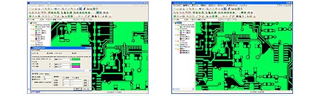
Simple Operation for Creating Double-Sided Board
|
|
After setting the line width and pad size,
you can easily create a single or double-sided board.
Simply double-click to switch top to bottom layer and
generate pad for through hole.
|
Enter Dimension at Keyboard
|
|
It is useful function for designing high-frequency
pattern to enter dimension at keyboard.
|
For Anyone Familiar with Mechanical CAD Software
|
|
EASY CAD have the valious editing commands
popular in mechanical CAD software:
extend line, parallel, corner round, corner bevel, move/copy
(straight, rotation, mirror), offset, hatch and so on.
|
Milling Line Creation
|
|
The milling lines for the cutter are created
automatically while applying a 1/2 offset for the milling
cutter channel width around the outside of the completed
pattern. If additional milling lines are created, unwanted
copper lamination can be removed.
|
Information
|
|
The X,Y coordinates of elements and the
distance between the centers of two elements or the
distance between their adjacent edges are displayed.
|
Truetype Font Support
|
|
You can enjoy to mill a variety of Truetype
Fonts.
|